By Dennis White, Director SAMCRA
Leaking pierce-fixed roofs following hailstorms Over this summer SAMCRA received a number of requests for assistance from
property owners whose mainly pierce-fixed roofs have leaked following hailstorms where fine hail has accumulated on the roof up to a depth of 40/50mm. On the Highveld this type of storm is not uncommon over a period of ten years or so. The root cause of
the leaks is that the hail reduces the water carrying capacity of the cladding thereby causing a buildup of water at the interface
between the melting hail and cladding which results in the development of a capillary siphon at the side-laps between adjacent sheets. The flatter the roof the more prevalent the leaks – a roof inclined at 10° has a drainage capacity 36% greater than one inclined at 5°.
The solution is to insert a butyl based sealer strip, preferably one with a reinforcing string, on the weather side of the fasteners along the entire length of the lap joint. In order to ensure the development of a continuous weatherproof seal we recommend that
stitching screws be installed, at no more than 600mm centres, between the fasteners anchoring the cladding to the supporting structure.
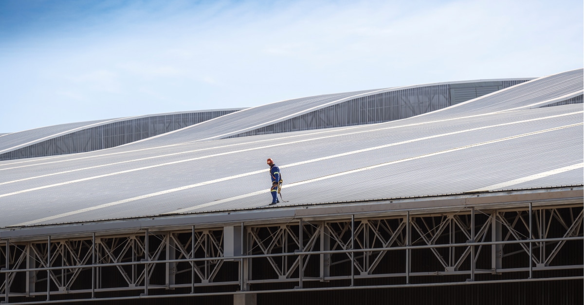
An area often overlooked is the top section of a curved roof which is effectively flat – the larger the radius the greater the extent of the ‘flat’ section. It is strongly recommended, as an absolute minimum, that a sealer strip be fitted in the side-laps from the crest to the point where the slope of the cladding is equal to the minimum slope for the respective profiles.
Weatherproofing of in-plane rooflights
SAMCRA also received enquiries pertaining to the weatherproofing of inplane rooflights and in particular those comprising polycarbonate material.
In-plane rooflights are those where the translucent material is made to the same profile as the roof cladding material and effectively replace a section of the cladding at the point where a rooflight is required as opposed to out-of-plane rooflights where the translucent component is fixed to a supporting frame, etc. which projects above the plane of the roof. In-plane rooflights are by far the preferred form of rooflight used in South Africa.
The most common in-plane rooflight configurations are:
• Chequer board
• Ridge to eaves
• Mid slope (a hybrid of chequerboard) and
• Ridge to eaves with portions of metal cladding at the ridge and eaves.
Whilst the chequerboard configuration is considered to provide the most even distribution of light it is the most difficult to weatherproof. A ridge to eaves configuration eliminates the problem of upslope metal to translucent lap joints but exposes the translucent cladding to the high wind loading at the eaves and to a lesser extent at the ridge. As translucent cladding is in the main non-trafficable the ridge to eaves configuration will inhibit access across a roof. Of the three configurations the mid slope is the most practical.
The two main factors that make it so difficult to weatherproof in-plane rooflights are differential thermal expansion and thickness of the translucent materials.
GRP (Glass Reinforced Plastic) and polycarbonate cladding have longitudinal coefficients of expansion of 2.5 and 5.6 six times respectively of that of steel. Surface temperature on a roof is considerably higher than ambient temperature. Surface temperatures of 60°C are common during the summer months. Heated through 60°C a 3.6m long metal sheet will expand 2.6mm
whereas a GRP sheet will expand 6.5mm and a polycarbonate sheet 14.6mm.
Assuming an operational range from 0° to 60°C and the cladding is installed at a temperature of 15°C the steel will expand/contract 1.9/0.6mm, the GRP 4.9/1.6mm and polycarbonate 10.9/3.6mm. The differential movement at the ends will be +1.5 –0.5mm for GRP and +4.5 –1.5mm for polycarbonate. GRP cladding will require a hole 3mm larger in diameter than the fastener and polycarbonate a 10mm slot. If the differential is not provided for, the translucent cladding will buckle between fasteners or may even crack. It is important to remember that the weatherproof seal on the underside of the metal washer of the primary fastener also has to accommodate this differential movement as does the sealer strip inserted in the end laps. With sealants transfers movement is directly related to thickness. A bead of sealant squashed to 2/3mm simply won’t cope. Based on this data we recommend that the lengths of GRP and polycarbonate profiled cladding be limited to 8.0m and 3.6m respectively.
Profiled translucent cladding is designed to fit over metal cladding, not under it.
This is the reason it is almost impossible to weatherproof a metal over translucent end lap. A more practical solution is to fix the translucent cladding over the metal cladding on all four sides and then back flash the upslope lap to the ridge.


