Project Type
Location
Steel Profiles Used
  • Date of Steelwork Completion
    2025-06-02
  • Tonnage
    200
Project Overview

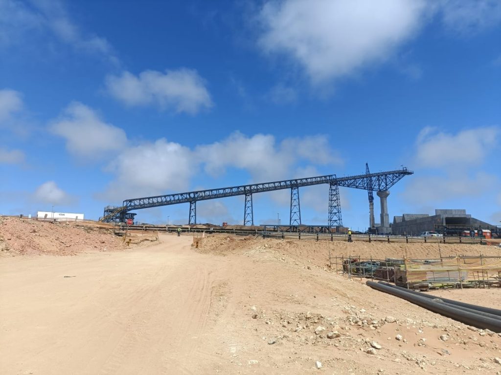
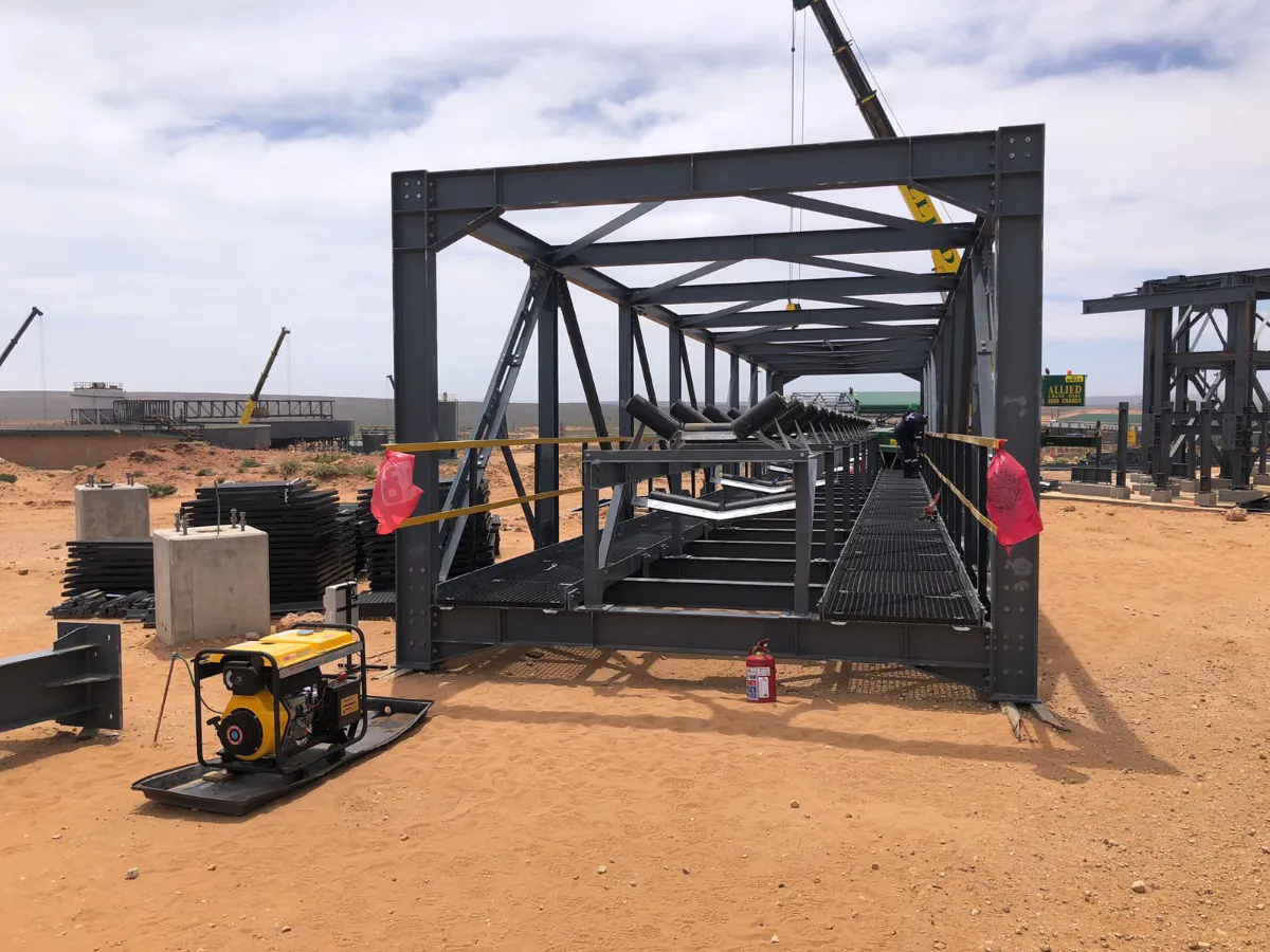
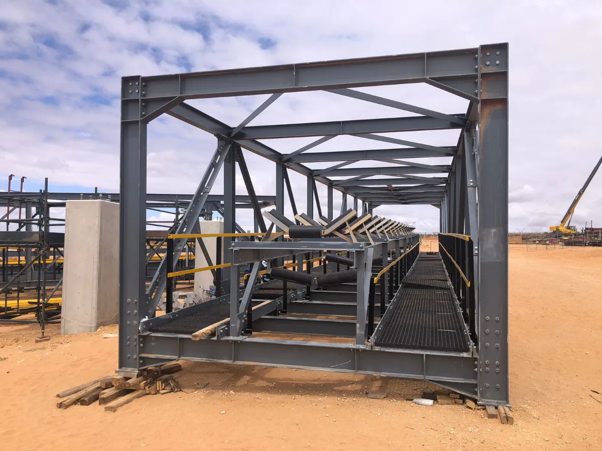
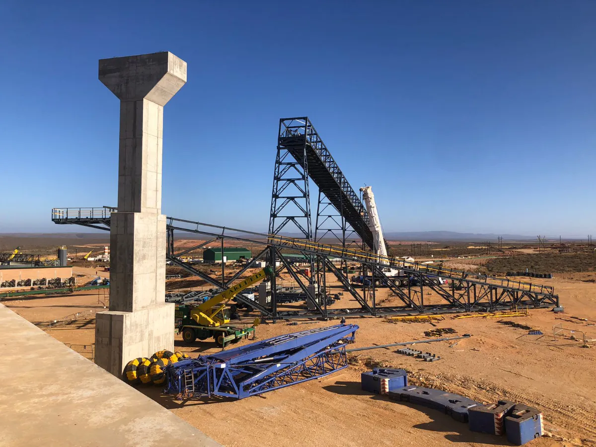
At Namakwa sands mine operated by Tronox the dune and natural sands are mined for heavy minerals. The sands are transported to a processing plant where the heavy minerals are extracted from the sand after which the sand is returned back to the mined area and the area is rehabilitated. The process of transporting the material from the mined area and returning it to the mined area is designed and specified by the mechanical engineer. In this case the mechanical engineer will design the material handling that defines the beltline, belt tensions and material flow through chutes. The Structural engineer will then design the structures to support the conveyor belt, chutes and mechanical equipment. In this conveyor it includes overland conveyor modules, elevated conveyor sections, belt tensioning structures (Horizontal and vertical take-ups), drive station, conveyor gantries, trestles, columns.

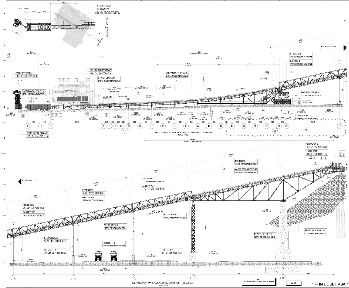
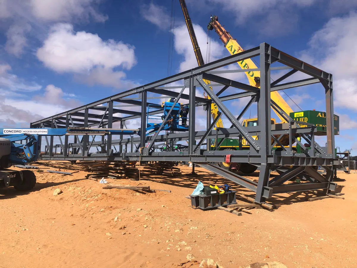
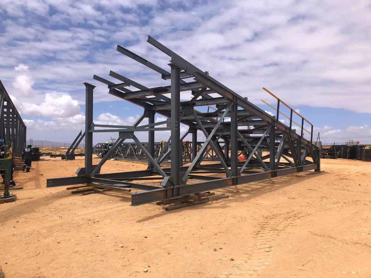
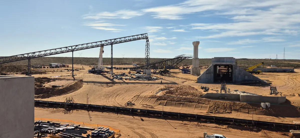
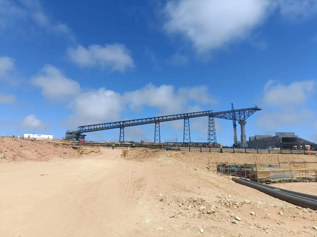
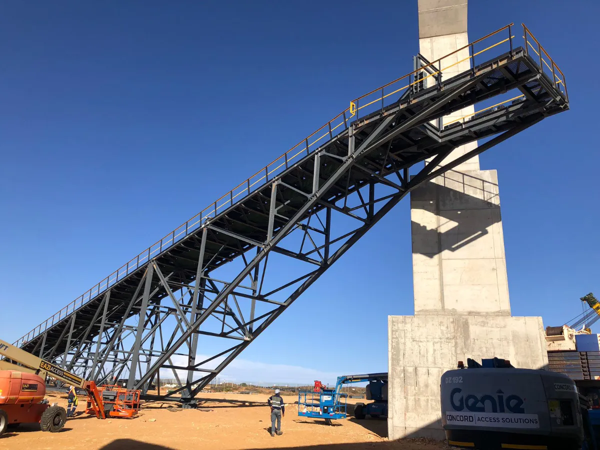
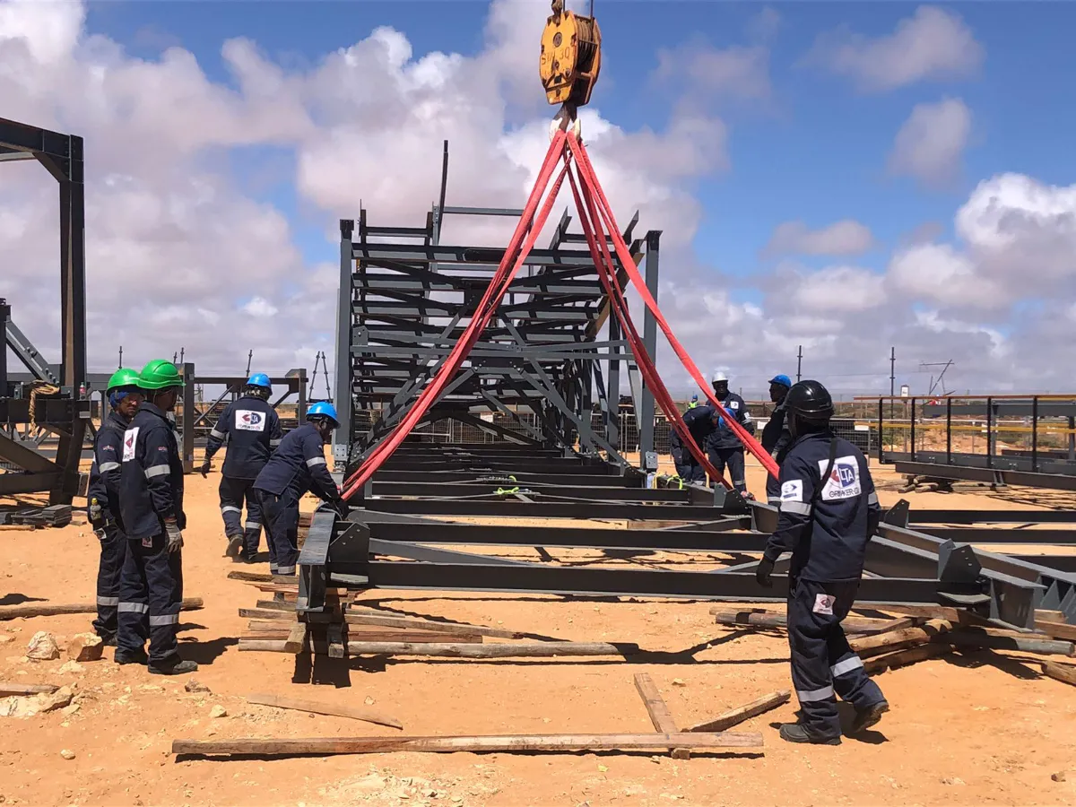
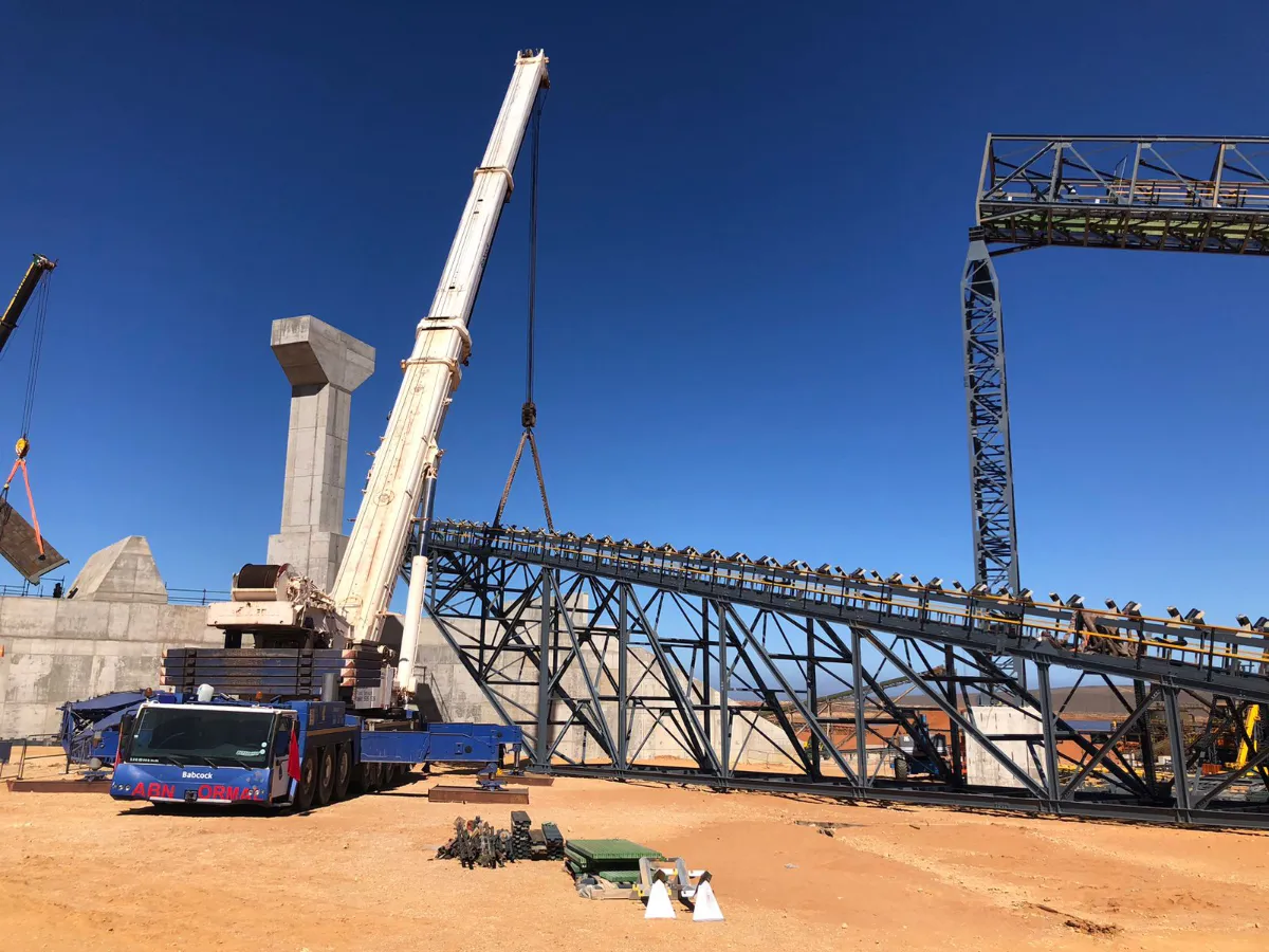
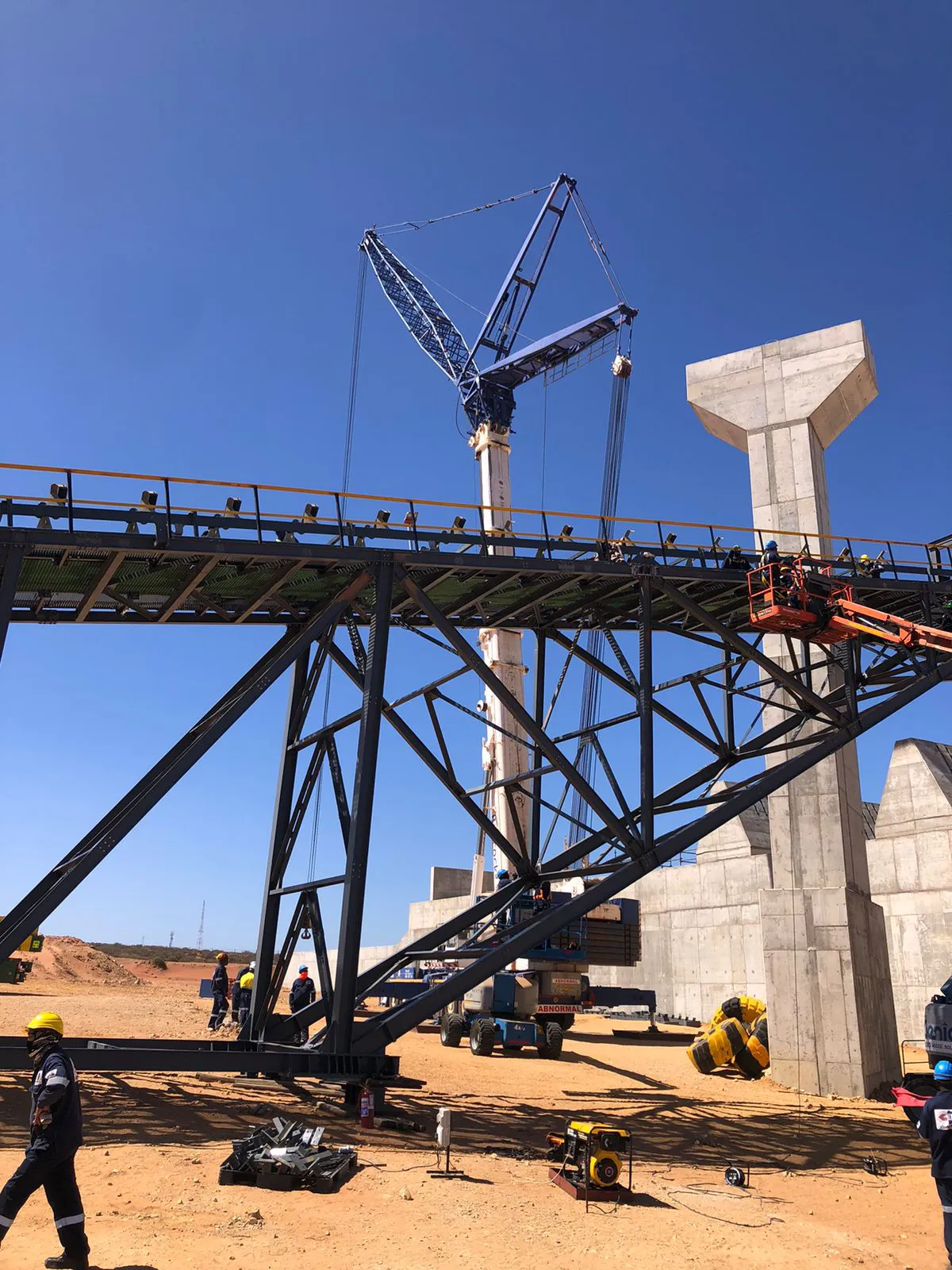
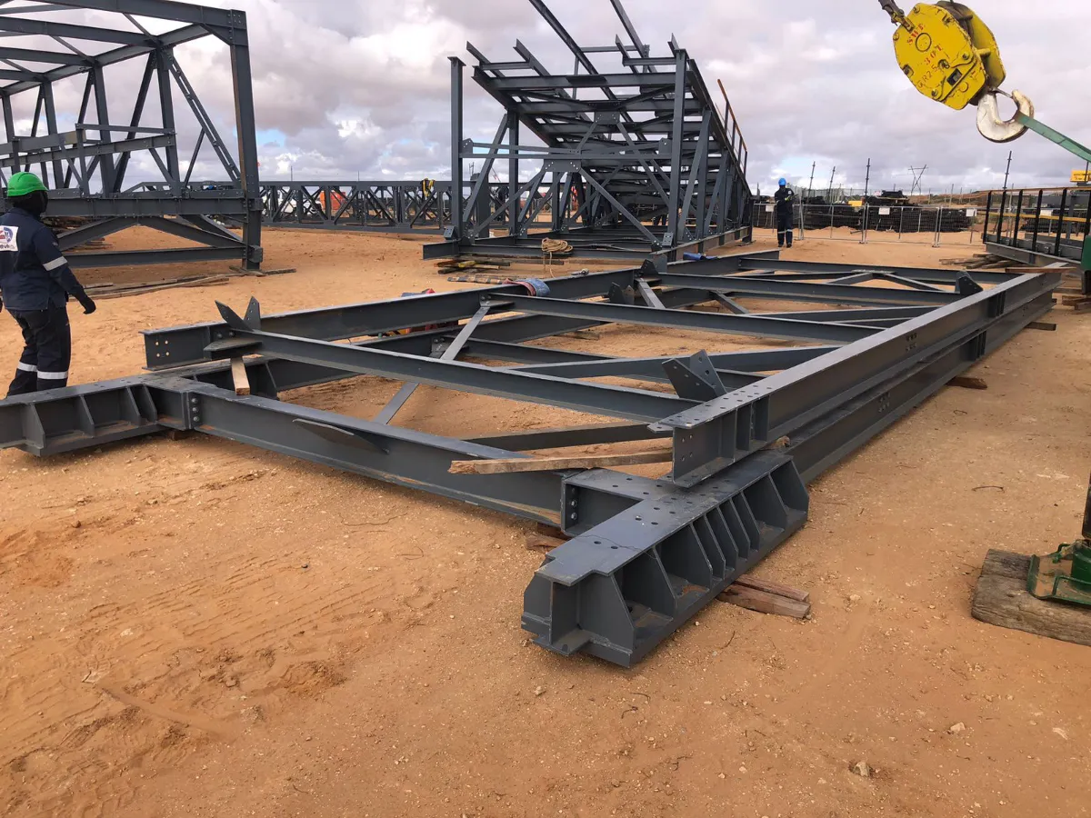
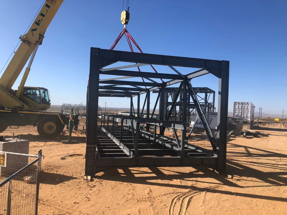
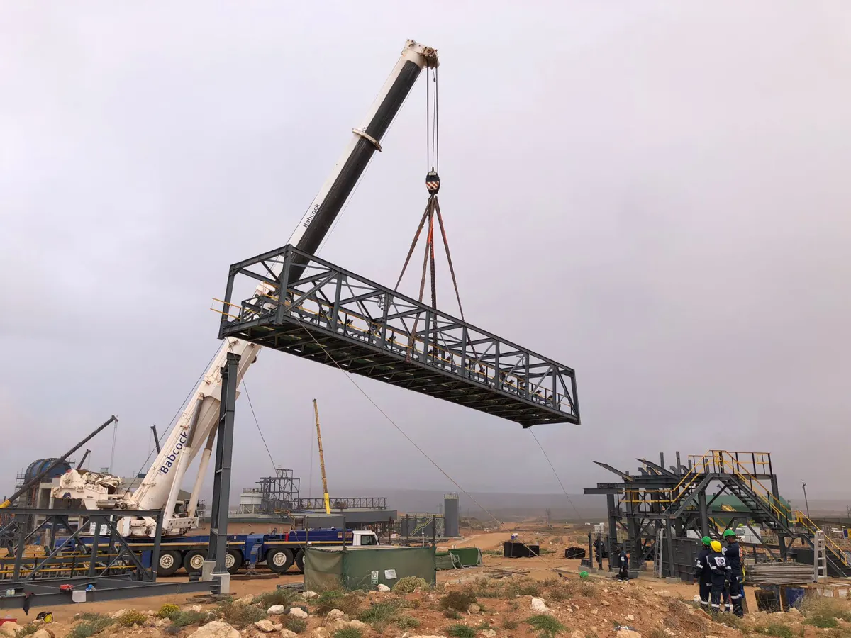
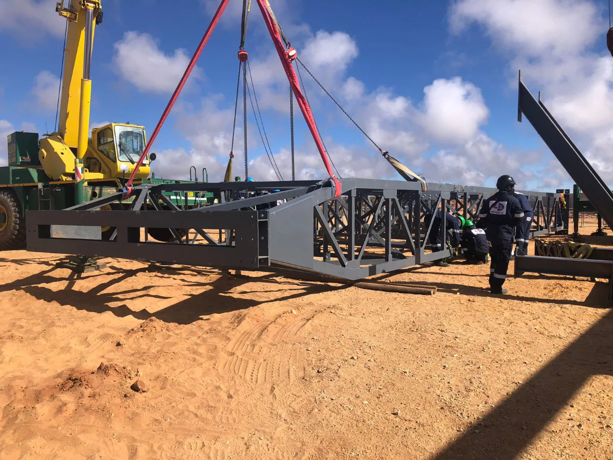
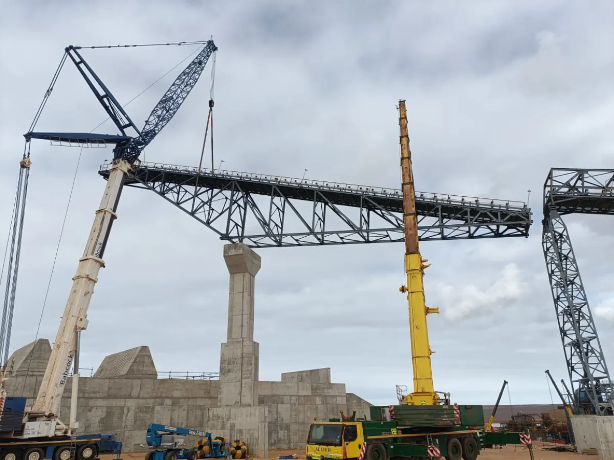
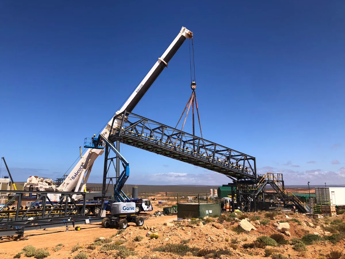
The brief for the structure is as follows: Elevate a 1050mm wide conveyor belt to an approximate height of 39m. Allow for a 20m cantilever on the head-end, which must accommodate the maximum stockpile dimensions that will peformed by the conveyor discharge. The structure must clear the maximum stockpile, at minimum angle of repose (i.e. cantilever slope must be sufficient to prevent the structure from being buried in material, later inducing draw-down loads). The centre-of-gravity of the head-end structure must fall within the support points of the main gantry to allow for pre-assembly of a stable structure. The head-end belt tensions must be transferred through the entire structure to the ground-level drive station, preventing any of this loading being transferred to the primary concrete trestle support, which would already be significantly loaded by the stockpile itself and therefore cannot accommodate the additional bending loads from the conveyor. Each structural element of the conveyor (especially the large head-end gantry) must be of a reasonable mass, such that each element can be pre-assembled on the ground and lifted into position at significant height using conventional mobile cranes.

This results in an efficient construction process. The main purpose of the rom stockpile feed conveyor is to convey run of mine material to a stockpile that provides a constant feed of material into the production plant.

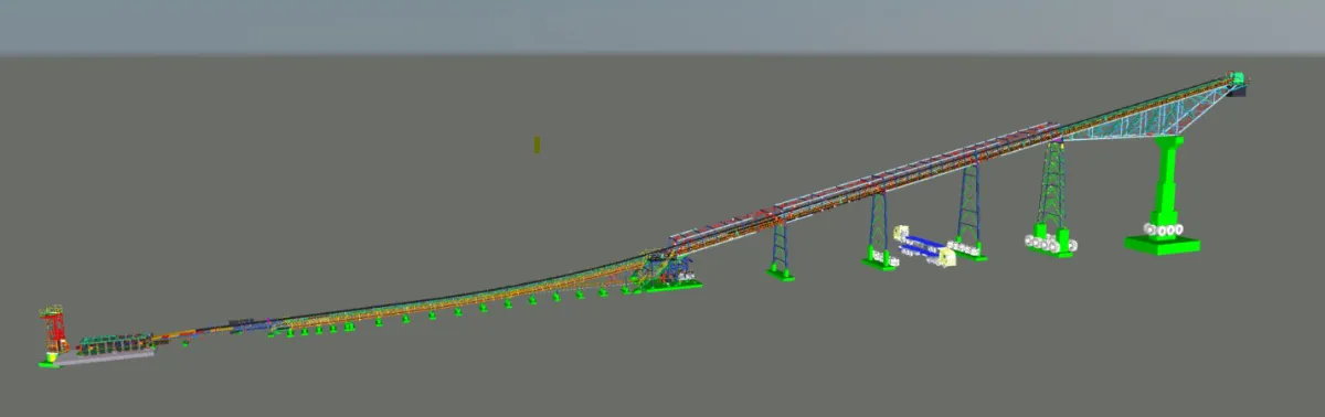
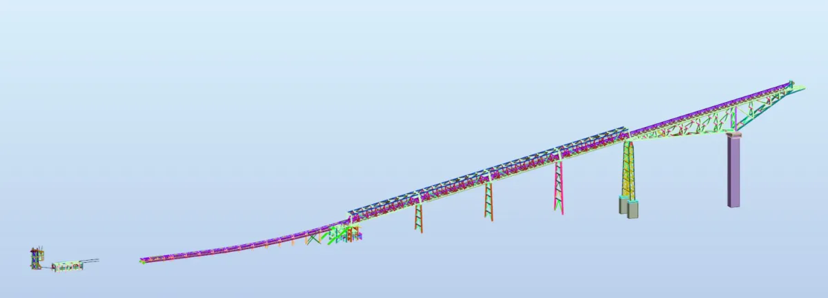
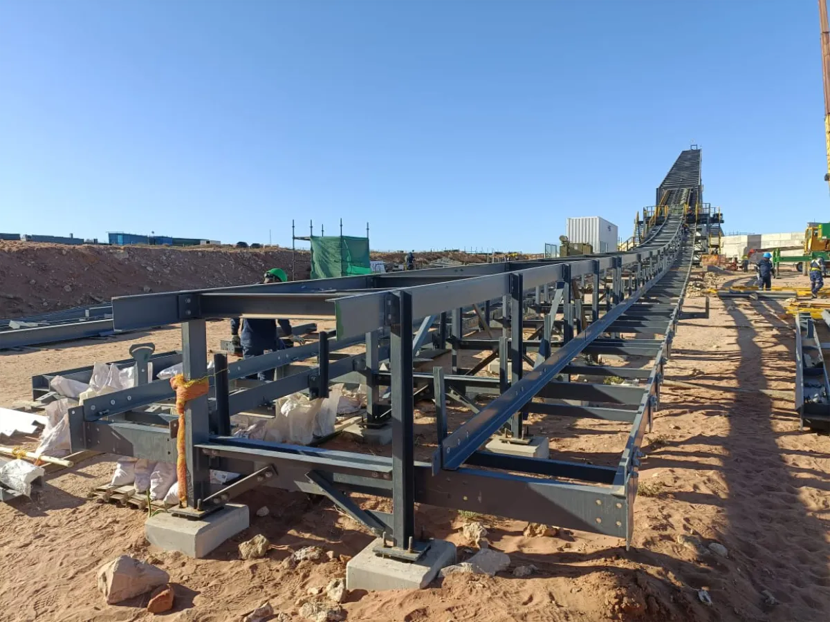
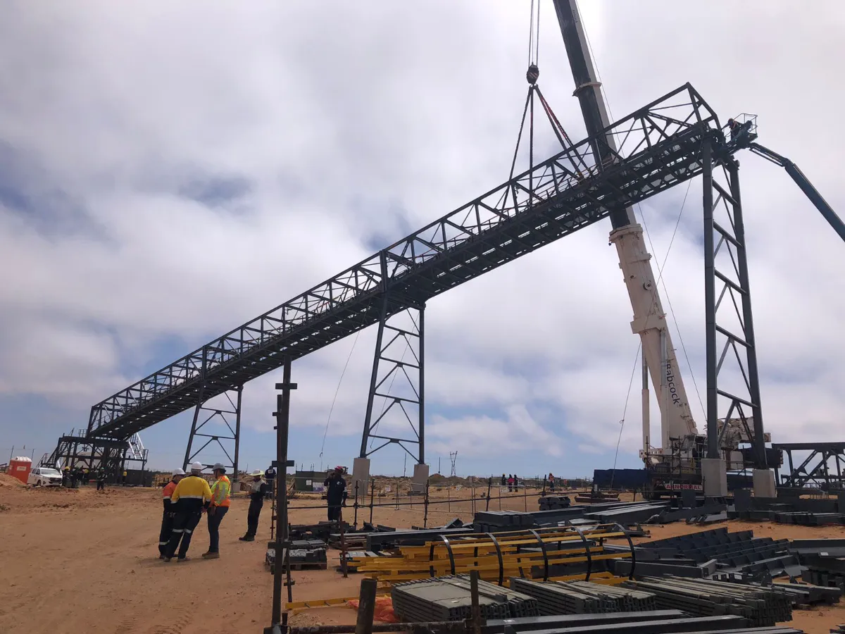
The conveyor starts with overland modules on the ground, as the height of the conveyor increases above ground level it changes to elevate sections and then becomes more economical to switch to 24m free spanning gantries supported on trestles. Once the conveyor extends over the stockpile its span increases to 35m and then cantilevers 24m to the centre of the stockpile. This portion of the gantry is an inverted box truss gantry that is supported on a concrete column that extends through the active stockpile to a concrete foundation below the stockpile.

Project Details
The structural steelwork on this conveyor was all fabricated in Gauteng and transported to Namakwa Sands at Brand se Baai. The gantries were assembled on the ground next to the installation location and then lifted into position by crane.Gantry 5 was the largest gantry and had was lifted into position using two cranes (tandem lift). Two cranes were available on site and the lifting points were optimised to utilise the capacity of the two cranes where 40 tons was allocated to the larger crane and the remaining 20 tons to the smaller crane. The lifting lugs and connections onto gantry 5 being part of lifting equipment required a safety factor of 5.6, this necessitated substantial stiffening of the loading point on the gantry.
The initial challenges involve the overall layout, where multiple constraints must be entertained: The stockpile capacity (and therefore height). The stockpile position is constrained by alignment with the downstream plant. The maximum allowable incline angle of the feed conveyor (12°). Intersection with the existing Dual Carry Conveyor at an extremely oblique angle (32° in plan). The minimum possible length of the feed conveyor (i.e. optimised) while fitting all necessary equipment (e.g. weigh-scale, feed chute etc.). Existing road clearance around the tail-end of the conveyor. Clearance of the existing servitude for the 132kV power line in the nearby vicinity.Additional road crossing underneath the feed conveyor. The above constraints required significant attention to ensure that the conveyor geometry was defined in a manner that would satisfy all necessary requirements. Structurally, the conveyor had to satisfy the following: Compliance to all client, SANS and legal requirements. Dual walkways, with the associated imposed live loading.Self-weight and live material loads, based on the design throughput of the conveyor. Large incrustation/spillage loads. Accommodation of belt tensions in the cantilever portion, along with predefined constraints on the length of the cantilever, with the additional constraint of clearance to the maximum possible stockpile size. All of the above difficulties/challenges/constraints were overcome through collaboration between multiple engineering and draughting disciplines, via the latest design software and a thorough review and quality control process.
Benefits of Steel in this Application

Steel, when designed in an optimal manner, serves to create high-strength, lightweight structural systems. This conveyor structure illustrates how steel can be used in complex arrangements/geometries, accommodating large and various loading types of varying magnitude. Steel provides flexibility in multiple categories, including literal flexibility(elasticity/plasticity), complex geometry (curves, multi-planar arrangements, connection methods - welding/bolting etc., and the ability to create an almost infinite set of arrangements using a relatively small set of standard elements/sizes).

This structure shows almost all of the benefits of steel (strength-to-weight, flexibility, accommodation of many possible coating systems and ultimately, the ability to suit a complex set of design, manufacturing, construction and layout requirements). A layout of this complexity would not otherwise be possible, were it not for this material.

Finally, while this structure is not designed for aesthetic purposes in the traditional, non-technical sense of the word, to those individuals who understand what this structure represents, its function and the effort required to produce it, it is beautiful in a way that the average person would easily overlook.

Annual Closure Notice

We will be closed from 12 December 2025 to 7 January 2026.

You are welcome to continue sending enquiries or membership applications, and you can still place orders online during this period. We will respond as soon as we return. Please note that any orders placed after 12 December 2025 will be fulfilled from 7 January 2026 onwards.