Tronox / Namaqua Sands / East OFS Project / ROM Stockpile Feed Conveyor

  • Date of Steelwork Completion
    2025-06-02
Project Type
Location
Steel Profiles Used
  • Date of Steelwork Completion
    2025-06-02
  • Tonnage
    200
Project Overview

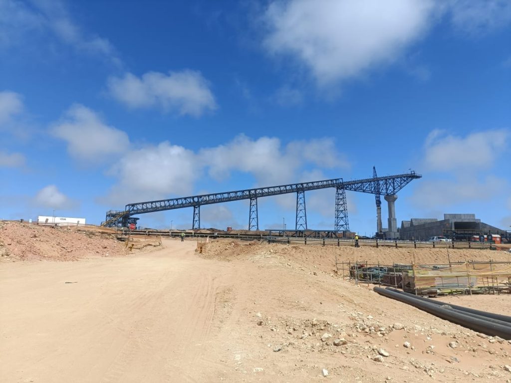
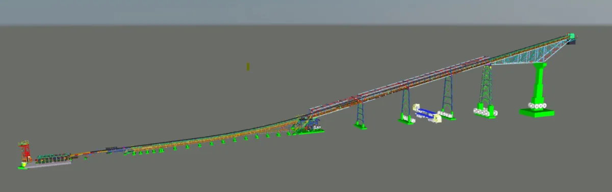
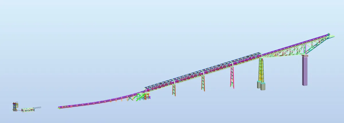
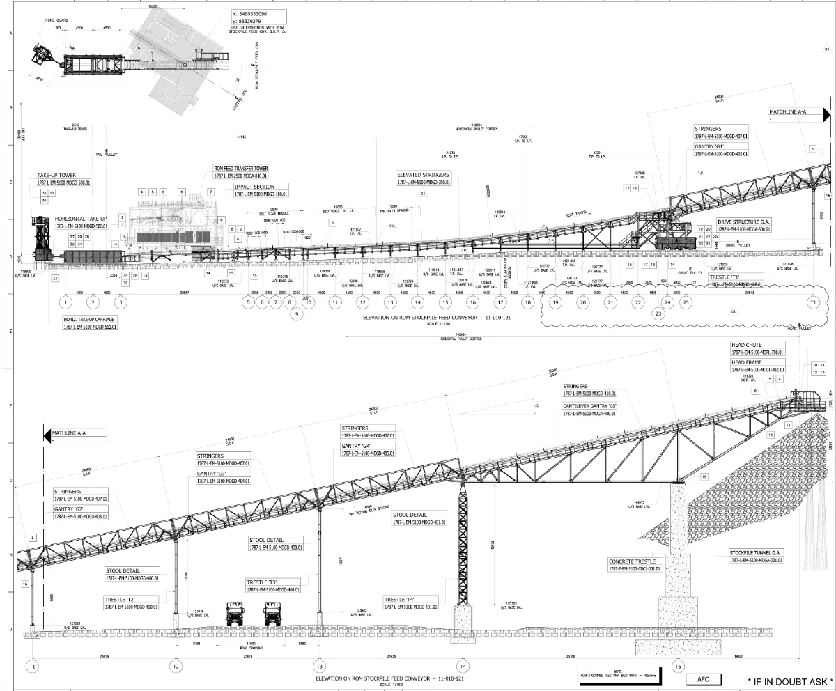
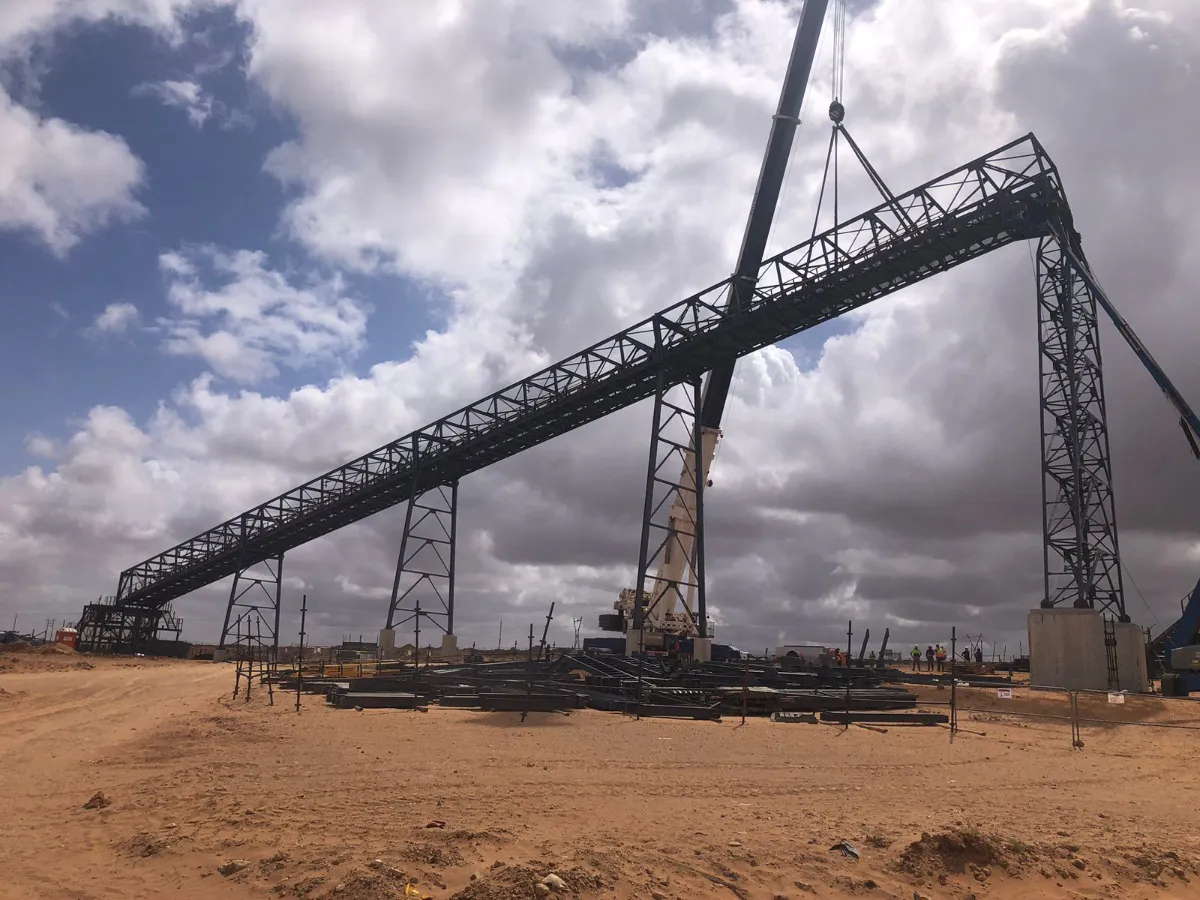
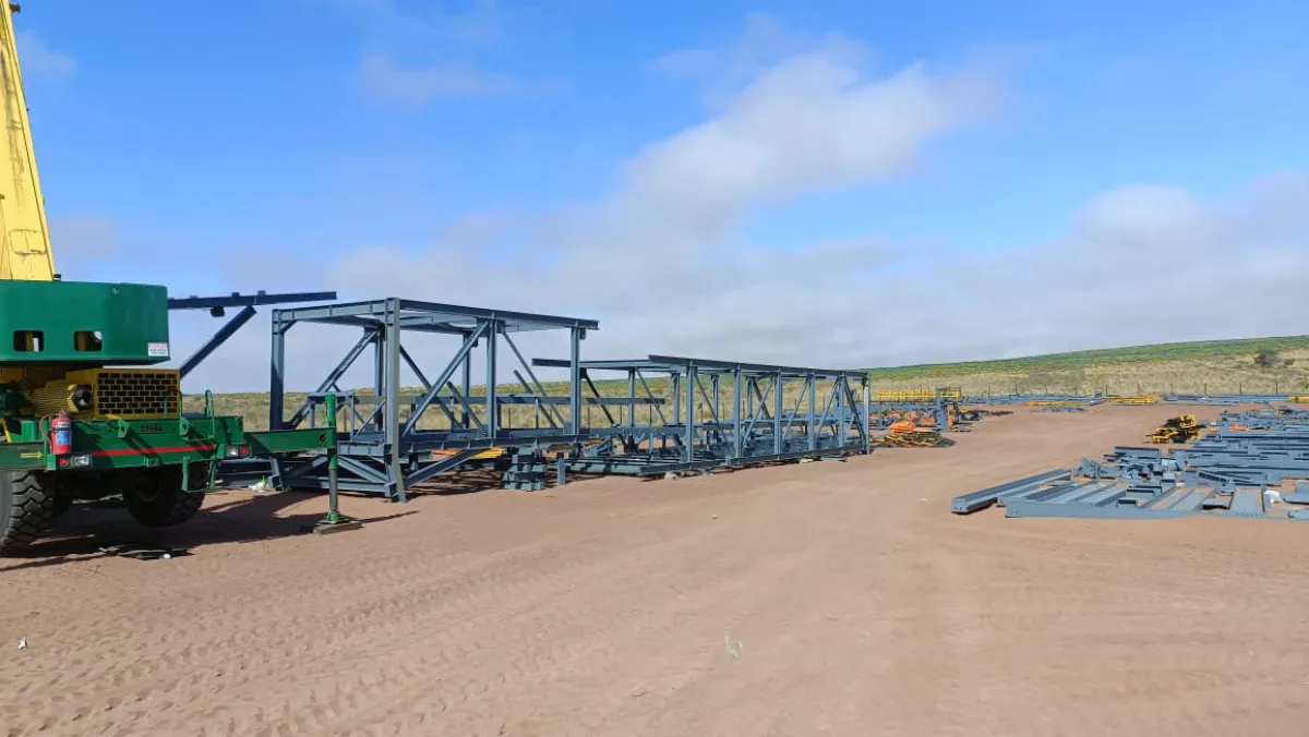
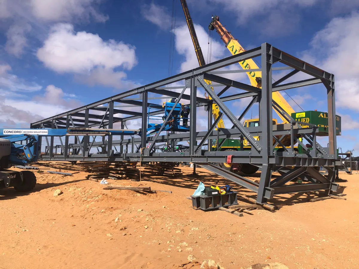
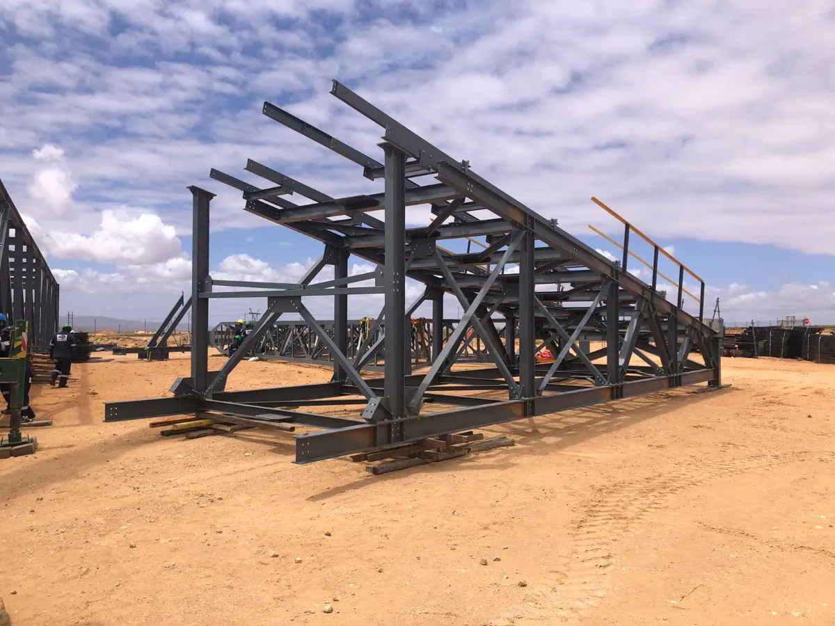
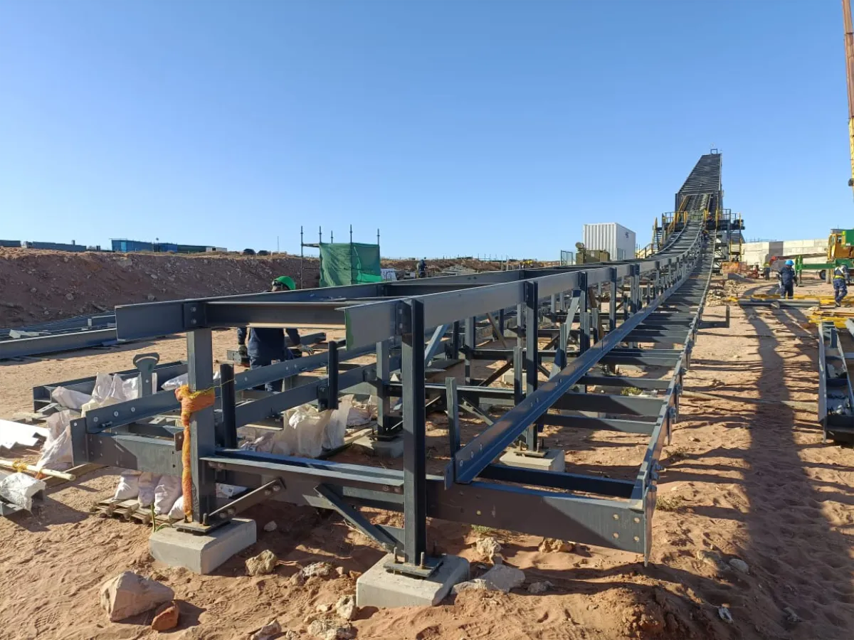
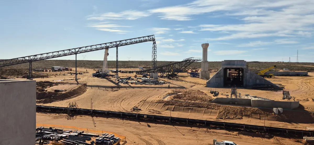
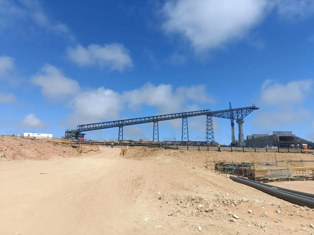
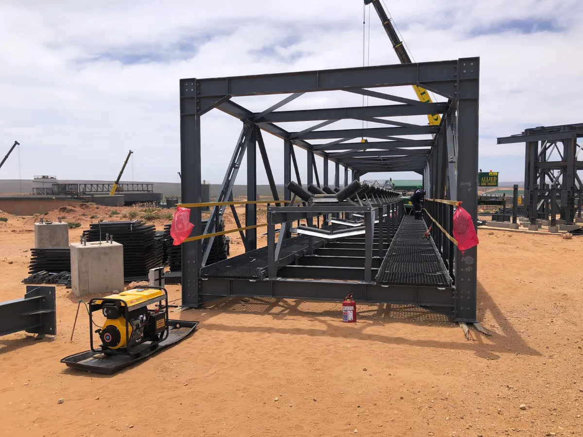
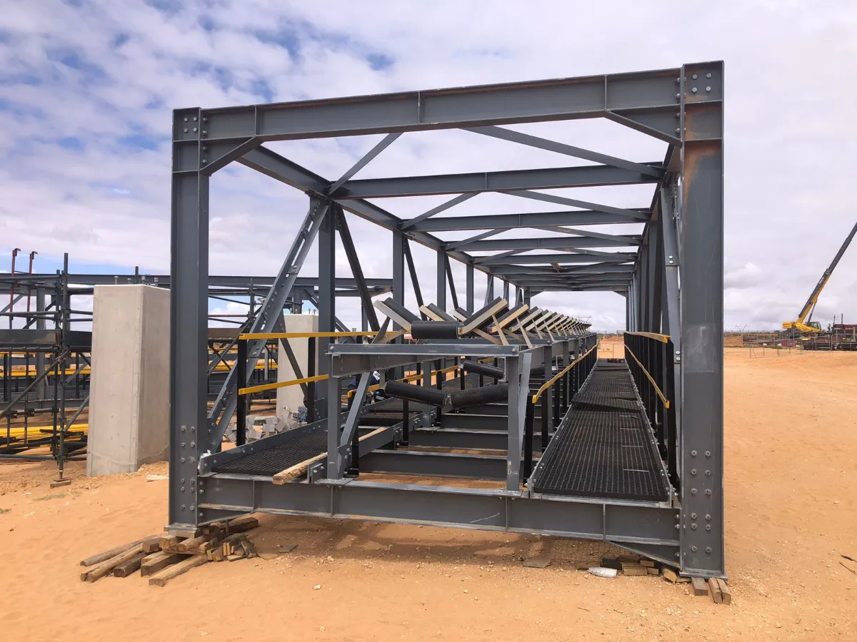
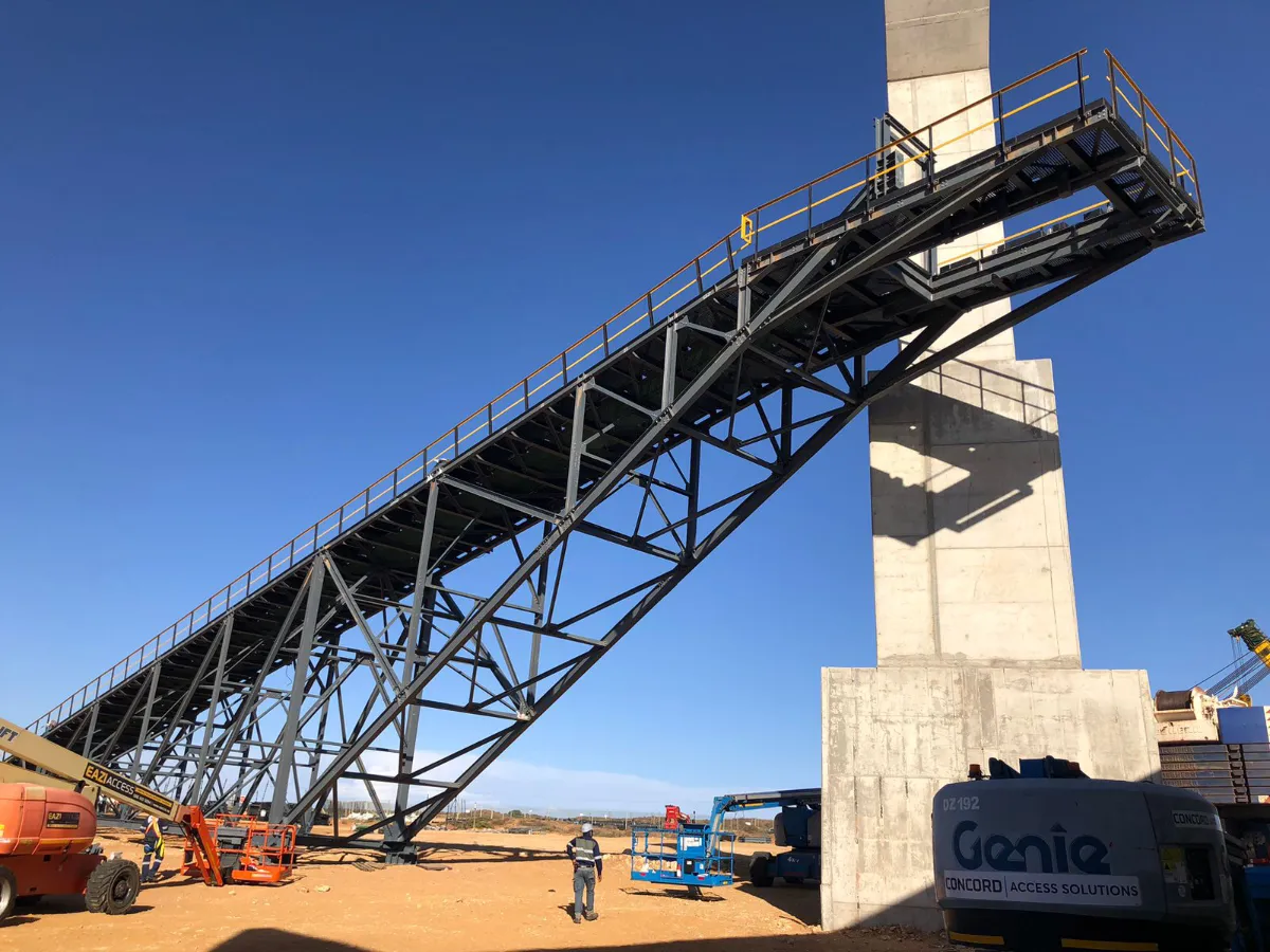
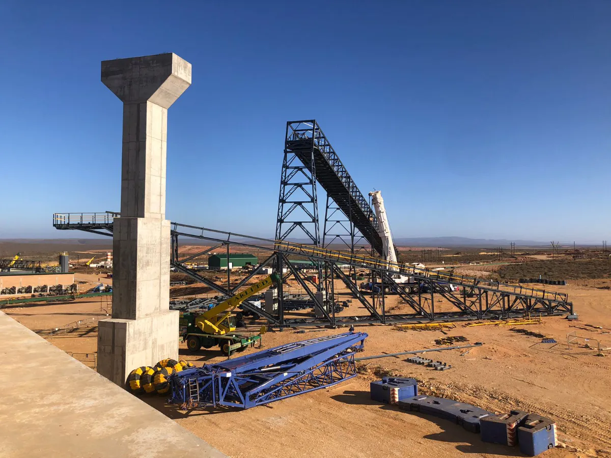
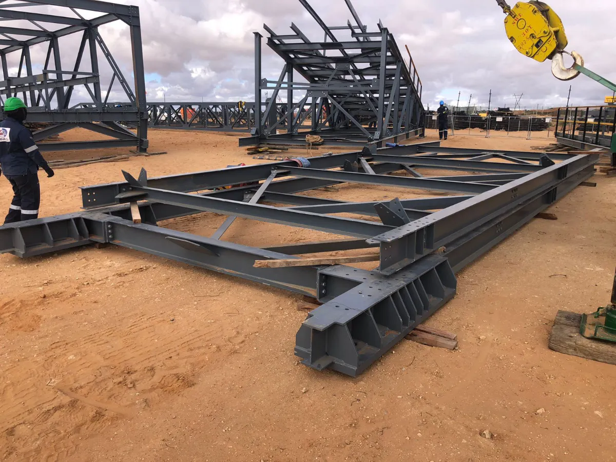
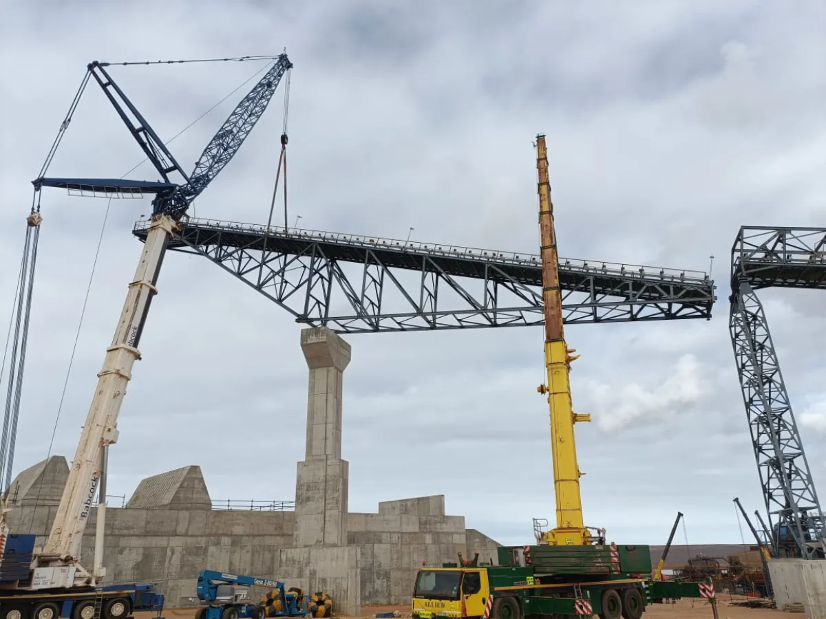
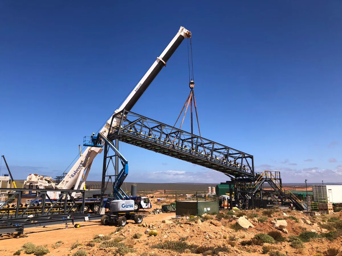
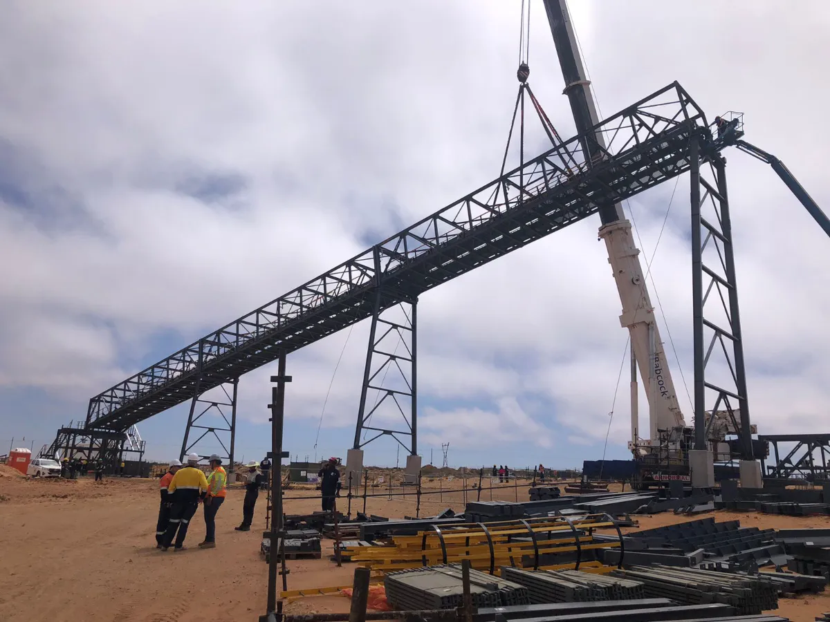
At Namakwa sands mine operated by Tronox the dune and natural sands are mined for heavy minerals. The sands are transported to a processing plant where the heavy minerals are extracted from the sand after which the sand is returned back to the mined area and the area is rehabilitated. The process of transporting the material from the mined area and

Project Details
The structural steelwork on this conveyor was all fabricated in Gauteng and transported to Namakwa Sands at Brand se Baai. The gantries were assembled on the ground next to the installation location and then lifted into position by crane.Gantry 5 was the largest gantry and had was lifted into position using two cranes (tandem lift). Two cranes were
The initial challenges involve the overall layout, where multiple constraints must be entertained: The stockpile capacity (and therefore height). The stockpile position is constrained by alignment with the downstream plant. The maximum allowable incline angle of the feed conveyor (12°). Intersection with the existing Dual Carry Conveyor at an extremely oblique angle (32° in plan). The minimum possible length of the feed conveyor (i.e. optimised) while fitting all necessary equipment (e.g. weigh-scale, feed chute etc.). Existing road clearance around the tail-end of the conveyor. Clearance of the existing servitude for the 132kV power line in the nearby vicinity.Additional road crossing underneath the feed conveyor. The above constraints required significant attention to ensure that the conveyor geometry was defined in a manner that would satisfy all necessary requirements. Structurally, the conveyor had to satisfy the following: Compliance to all client, SANS and legal requirements. Dual walkways, with the associated imposed live loading.Self-weight and live material loads, based on the design throughput of the conveyor. Large incrustation/spillage loads. Accommodation of belt tensions in the cantilever portion, along with predefined constraints on the length of the cantilever, with the additional constraint of clearance to the maximum possible stockpile size. All of the above difficulties/challenges/constraints were overcome through collaboration between multiple engineering and draughting disciplines, via the latest design software and a thorough review and quality control process.
Benefits of Steel in this Application

Steel, when designed in an optimal manner, serves to create high-strength, lightweight structural systems. This conveyor structure illustrates how steel can be used in complex arrangements/geometries, accommodating large and various loading types of varying magnitude. Steel provides flexibility in multiple categories, including literal flexibility(elasticity/plasticity), complex geometry (curves, multi-planar arrangements, connection methods - welding/bolting etc., and the ability to create an almost infinite set of arrangements using a relatively small set of standard elements/sizes).

This structure shows almost all of the benefits of steel (strength-to-weight, flexibility, accommodation of many possible coating systems and ultimately, the ability to suit a complex set of design, manufacturing, construction and layout requirements). A layout of this complexity would not otherwise be possible, were it not for this material.

Finally, while this structure is not designed for aesthetic purposes in the traditional, non-technical sense of the word, to those individuals who understand what this structure represents, its function and the effort required to produce it, it is beautiful in a way that the average person would easily overlook.