


[vc_row][vc_column][vc_column_text]PLATE GIRDERS (BEAMS AND COLUMNS)
The most important issue that detailers overlook (possibly caused by the engineers as well) is the installation of web stiffeners (both load carrying and web shear).
Whilst in theory plate girder webs with a relatively thin ratio of thickness to height can be made to be structurally suitable with the addition of web stiffeners, engineers often overlook the difficulty of keeping the web suitably straight to conform to the manufacturing requirements of SANS 2001 CS1. This requirement is based on the web height d/150 or 3mm which-ever is the greater measured over a gauge length equal to the height of the web.

For a 750mm high x 8mm thick web, with lots of web stiffeners, the 5mm straightness of web requirement on the gauge length equal to the height of the web can be very difficult to achieve, especially if full penetration web-to-flange welds and continuous welding of the web stiffeners is the requirement. For engineers, it is worth noting that the cost of fitting a stiffener is high. In this example, a pair of full height stiffeners could be of the order of R500.00. It does not take too many stiffener omissions to justify a thicker, un-stiffened web which will present far fewer distortion issues. Check this out with your friendly steelwork contractor.
Even though the allowable out of straightness and squareness requirement for plate girder flanges (see figures 2, 3 and 4) seem quite reasonable for ‘ordinary plate girders’, the requirements for crane girders are much tougher.
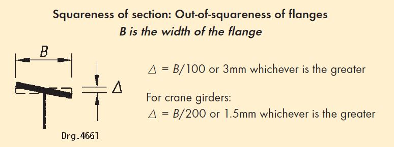
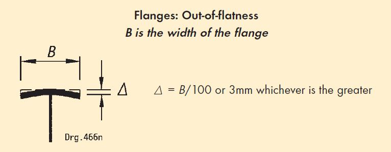
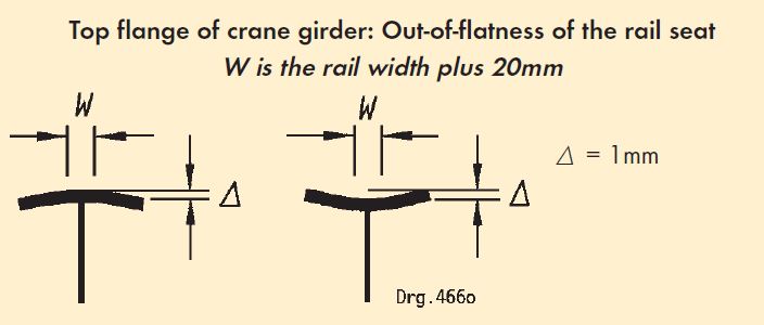
Draughtsmen should get into the habit of calling up these tolerances for crane girders to impress upon the works the importance of crane girder manufacturing and meeting the tolerance requirements. Bear in mind serviceability issues could well over-rule SANS 2001 CS1 such as when the beam is to be used for a floor beam with a rigid flooring material such as grating.
Note: All these distortion issues could be exacerbated by hot dip galvanizing where the watch -ord should be minimum welding.The other pertinent issues regarding plate girders are when they are used for crane girders. It is good practice from a fatigue point of view to have a full penetration weld between the web and the top flange of plate girders intended for crane use. Often designers call up part height stiffeners to prevent rotation of the top flange of crane girders under horizontal transverse loads which get omitted by the detailers.
Full height stiffeners must always stop short of the bottom flange (20mm is a good number but the gap should not exceed 4 times the web thickness) except for the end load bearing stiffener(s).
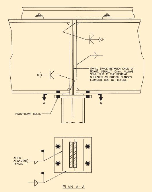
Design engineers need to be aware that except for the lightest application cranes, crane girders at their supports must be able to rotate in the vertical plane under load in order not to create a fatigue situation. We recommend that the crane girder end plate should extend down and below the bottom flange of the girder to create a “rocking plate” that will allow the rotation to happen. An example of this type of detail is shown in figure 5.
Alternatively, a rocker plate can be welded to the cap plate of the column. Be careful not to bolt through this rocker plate. This also presupposes that the tie back plate between the crane girder and the column (the diaphragm as we used to know it) can also accommodate rotations in all three directions.
Editor’s note: watch out for the SAISC courses in July 2008 on the design of heavy (crane supporting) structures. This course was well received when offered in 2007 for the first time. All of these issues and many others will be covered during the course.
PLATE GIRDER COLUMNS
Few engineers call up the size of the weld required between the flanges and the webs of plate girder columns. The calculation is simple. Calculate the share of the forces that are carried by a single flange. The amount of welding required should just be sufficient to prevent the flange from tearing away from the web under this load. Almost inevitably a minimum size weld is required. This is controlled by the need for not having too small a weld that during cooling the weld will not crack.
(Refer to the table 6.26 in the “Red book” for the minimum size welds suggested for a given thickness).
SAG SYSTEMS AND COLD FORMED PURLINS AND GIRTS
A common cry I hear from engineers is that contractors supply the wrong grade of steel for purlins. Engineers tend to have a typical note on their drawing which calls for all steel to be grade 350 WA (S355JR in the future). Draughtsmen typically do not call up any grade of steel on their drawings but especially ignore the grade on purlin drawings.
It is very necessary for draughtsmen to call up the correct grade of steel the designer requests for his purlins, both on drawings, cutting lists, and material order forms. The engineer must be alert to this issue when he checks computer generated drawings as I am sure the tendency is for the engineer not to bother to check the purlin drawings, after what could possibly go wrong with purlin details!
It is very necessary for the contractor to ensure that he orders the correct grade of steel for his cold formed profiles. The cold formed suppliers will supply commercial grade steel for their profiles unless specifically instructed and priced otherwise. Grade 300 W equivalent purlins are available but usually at a premium and sometimes an extended delivery, so Mr. Contractor, please speak to your friendly cold formed supplier or to the engineer to get his permission to change to a lower-graded steel.
This is one of the most common issues that are overlooked by engineers whilst checking detailed drawings or where bad practice is employed by draughtsmen. The issues relating to sag systems and cold rolled purlins are:
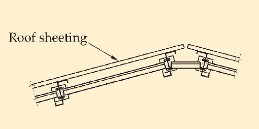
That unless a sag system is tied to an equal and opposite system on the other side of the apex of a roof (see figure 6) and almost always on side sheeting panels, it is necessary to brace the system back with diagonal sag members (ties) running outwards and upwards to the supports to create a lattice girder to prevent the purlins/ girts from sagging parallel to each other as shown in the example (see figure 8).

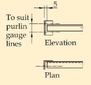
Note: The connection between the diagonal ties and the purlin is one place where it is difficult to make the centre of gravity lines of the components meet in a common centroid. Eccentricities can or will occur and are usually acceptable due to the closeness of the connection to the column centre line. Please check this out with the engineer before proceeding. It is good practice to have an extended end angle for sag members when used with big cold formed members per the example (see figure 7) Note the suggestion to keep the bolt centres on the same centres as the purlin to cleat connection for improved workshop productivity. Keep the bolt diameters the same for maximum productivity benefits.
Editors note: If there are any issues that you think Spencer has overlooked or do you have experiences you would like to share with our readers please forward them to us. We would gladly acknowledge the source if required or pass it on anonymously.
Since the first article in the series was published several engineers have raised subjects that I would not have thought of so we can all learn from their experiences:
BEWARE OF SLOTTED HOLES
Only too often in the real world to accommodate the out of (steel) tolerance we expect when interfacing with concrete detail draughtsmen call up slotted holes to accommodate the expected adjustment. Very often they can be injudiciously placed making the engineers design concept null and void. A real life experience of this is a conical roof with radial parallel chorded trusses where both the top and bottom chord are transmitting forces into the concrete ring beam and column support. In this case the top bracket sitting above the concrete and the bottom bracket connected to the side of the concrete.
The detailer called up slotted holes in the base plate of the top chord and packers to make up the expected gap at bottom chord. The erector was very grateful to the detailer for the slotted holes which generally were suitable to accommodate the out of position bolts.
So what went wrong? As the loads came on the force in the shoe’s horizontal component rose and the shoe just kept moving out as long as the slot allowed for it.
What should they have done? Simply a welded washer plate with a round hole should have been welded to the top base plate of the shoe and then the nut should have been tightened to prevent this movement.
Constructing roofs where the trusses are designed for continuity and the longitudinal girders are also designed for continuity.
No matter how tempting it might appear to the draughtsman and maybe even more so for the erector no slotted holes can be allowed in the continuity joints. Great care should be taken in the shops to see that the connections will and do fit properly on site, and because of the continuity it is advisable to call up non slip connections. If the connections do slip, continuity cannot be guaranteed.
There is a special consideration that erectors should be advised of by the engineer and draughtsman with a special note on the erection drawing where continuous lattice girders are used. It is essential that the girder erection be at least three bays ahead of the truss installation to enable the girder system to behave continuously. This means that all connection bolts are fully tightened. The reasoning behind this is that, for instance if the girder is erected and the trusses installed before the next girder is erected, then that girder knows no better than to act as a simply supported member. To get it to behave as a continuous member it would be necessary to somehow manually induce the continuity forces and then tighten the bolts, which to the writer seems impossible to do. You have been warned…[/vc_column_text][/vc_column][/vc_row][vc_row][vc_column width=”5/6″][vc_cta h2=””]By Spencer Erling, Education Director, SAISC[/vc_cta][/vc_column][vc_column width=”1/6″][vc_single_image image=”4609″][/vc_column][/vc_row]